A junction circulator is a 3-port device formed by a symmetrical Y junction coupled to magnetically biased ferrite material. The circulator permits flow of microwave energy in one direction only, e.g. from port 1 to 2, 2 to 3, and 3 to 1. When one of the ports is terminated (matched condition) the other two are isolated in the reverse direction. Thus an isolator is a circulator which has a matched termination, usually integral to the unit, on port 3.
The ferrite circulator is the basic building block of the ferrite components described herein. Combining basic junction selections, it becomes possible to perform more complex functions and/or improve performance.
Applications of the circulator include: coupling element for reactance amplifiers (paramps and TDA’s), duplexing and phase lock injection. Due to practical restrictions, a single junction isolator will typically provide 20 dB of isolation. Multiples of this value are obtained by cascading sections together in a single package.
SELECTING THE DEVICE
 |
The most misunderstood concept of circulators is that of isolation. Circulators do not provide isolation until they are terminated, and then the isolation between any two ports ( in the direction opposing the direction of circulation) is the return loss due to third port mismatch. This basic relationship is shown in Figure 1.
Assuming that Port 3 is terminated by a perfect 50 ohm termination, the isolation is simply a function of the circulator VSWR. In order to achieve a given amount of isolation, it is necessary to select a circulator which is sufficiently well matched to meet the requirements. Practical limitations (frequency coverage, temperature, etc.) however, do not allow for this procedure to be used ad infinitum – sometimes it becomes necessary to cascade circulator sections into multiport devices.
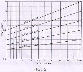 |
If a circulator is used as an isolator (for load VSWR reduction purposes) and the third port is assumed to be terminated by a perfect termination, Figure 2 applies. The input VSWR vs. load VSWR is shown for a number of different degrees of circulator match. It is often possible to specify a desired degree of match (on a special order basis). If the device is used as an isolator, however, it is usually easier to buy it as such.
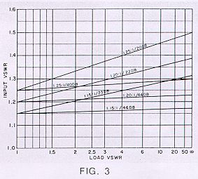 |
Figure 3 shows the VSWR reduction properties of some practical isolators. Some of the configurations shown are available on a special order basis only, while others shown are met by standard catalog items.
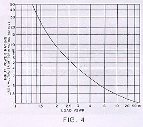
When an isolator is used, consideration must be given to the power handling capability of the integral termination supplied. Figure 4 gives the input power rating (as a multiplier of termination rating) vs. load VSWR. All standard isolators carry a minimum termination rating of 1 watt and many will handle 2 watts. For details and information on higher power terminations, consult the factory.
 |
Specifications shown for various types are normal production variation limits. Improved performance is available over narrower frequency ranges, reduced environments, etc. Special techniques can also be used to optimize specific parameters, i.e. loss, isolation or VSWR.
Most of the devices shown are useable over normally encountered temperature variations. Especially wide variations or operation at constant abnormal temperatures should be specified.
All units are normally semi-shielded for operation of the units in close proximity to one another, large ferrous objects or when exposed to moderate external magnetic fields. Specially designed units are available where highly shielded units are required.Standard connector types are N and SMA female. Male connectors and other types are available on request.